Description of the settings that enable direct communication between the Vocera HL7 Adapter and the Vocera Platform.
-
Navigate to the New Adapter option, or navigate to an existing adapter to edit.
See Creating a New Adapter and Editing an Adapter for instruction as needed.
The configuration fields are the same for new and existing adapters.
-
Complete the Outbound Connection configuration
settings.
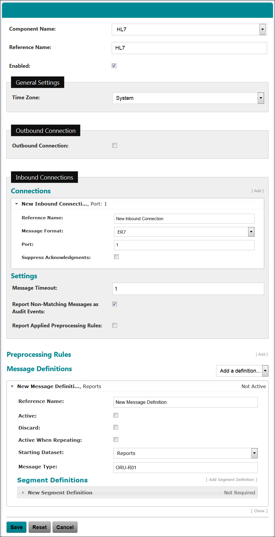
Outbound Connection Configuration Fields Description Outbound Connection Vocera Platform can use an outbound connection to communicate with an HL7 server for processing outbound messages. Configure the outbound connection with the following information.
At least one connection, inbound or outbound, must be configured for the Vocera HL7 Adapter to function. If Outbound Connection is unchecked, an inbound connection and message type are created in the system by default.
When sending outbound HL7 messages, a version of 2.3 is used by default in the message header of each message sent. If required, the version sent may be adjusted by an implementation specialist via a configurable interface property.
Message Format Select the message format (ER7 or XML) that this facility will use for this outbound connection. This field is required.
Server Name Enter the host name or IP address of the server to which the outbound connection will connect. This field is required and must be a valid server name for an outbound connection.
Port Enter the server port on which HL7 messages and acknowledgments are transmitted. This field is required and must be a number between 1 and 65535.
-
Complete the Inbound Connections configuration
settings.
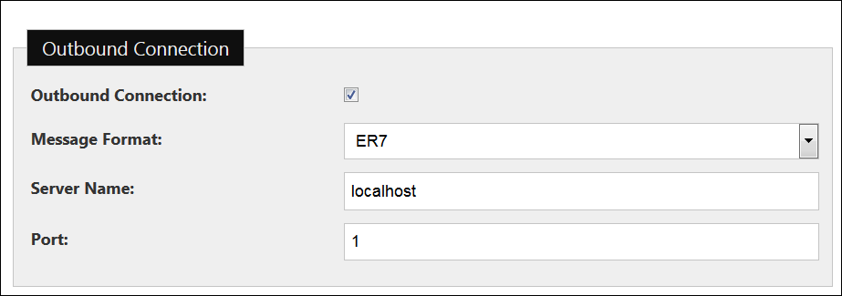
Configure one or more connections for processing inbound HL7 messages. At least one connection, inbound or outbound, must be configured for the Vocera HL7 Adapter to function. If Outbound Connection is unchecked, an inbound connection and message type are created in the system by default.
Click Add to create an inbound connection, and the configuration fields shown below display. Click to expand an existing connection and edit the configuration, or click Add to create additional inbound connections to support additional HL7 servers.
Click Remove to delete a specific inbound connection. The last inbound connection can only be removed if there is an outbound connection; the Remove option is not displayed in this event.
Inbound Connections Configuration Fields Description Reference Name Enter a descriptive name for the collection of settings that define this connection. Message Format Select the message format (ER7 or XML) that this facility will use for this inbound connection. This field is required. Port Enter the server port on which HL7 messages and acknowledgments are transmitted. This field is required and must be a number between 1 and 65535.
It is recommended that each connected system be assigned to a separate port. The number for threads available for processing inbound messages is proportional to the number of available ports, and the reporting of inactivity is also by port.
The thread pool that handles connections and the initial reading of messages has a limited number of threads per inbound connection. It is designed to handle no more than two actual network connections per configured "inbound connection", which implies each connecting system should have a separate inbound connection configured.
In addition, detection of idle input is done separately for each configured inbound connection. If multiple systems connect to the same inbound connection port and one of them gets into a bad state where it is no longer sending messages, it would not be noticed if the other systems on the same inbound connection continue processing successfully.
Suppress Acknowledgments Select this checkbox to prevent the adapter from sending HL7 acknowledgments in response to messages on inbound connections. This option may be useful for older versions of the Philips patient monitoring systems.
Message Timeout Enter the number of minutes expected to elapse between messages. The value must be a number between 1 and 10000. When this timeout period is exceeded, audit event 600 is generated to report that the connection is idle.
Report Non-Matching Messages as Audit Events Check this box if the system should log an audit event when a received message does not match a message definition.
Report Applied Preprocessing Rules Check this box if the system should log an audit event when a preprocessing rule changes a message's content.
-
Complete the Preprocessing Rules configuration
settings.
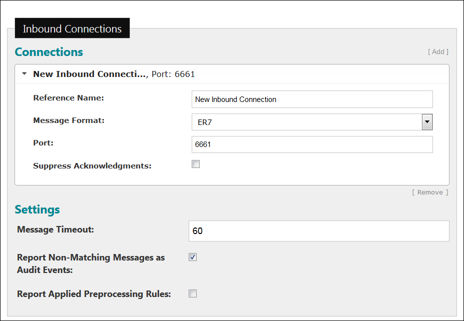
Preprocessing rules are used to modify non-standard received messages before they are matched against configured message definitions. Configure one or more preprocessing rules.
The preprocessing rules are applied, in listed order, when a message is first received on an inbound connection as follows:
- A message is received.
- Each subsequent incidence of the received message that matches the regular expression is replaced by the replacement string, creating a new message.
- Repeat steps a and b for each preprocessing rule in listed order on the new message.
- Match the new message against the configured message definitions.
Expand an existing preprocessing rule to edit the configuration, or click Add to create additional preprocessing rules. Click Remove to delete a specific preprocessing rule.
Preprocessing Rules Configuration Fields Description Purpose Enter the purpose of the preprocessing rule. This field is required. The purpose should concisely describe the rule and be easily understood.
Active Select the Active checkbox to allow this preprocessing rule to be used in the facility's HL7 implementation.
Regex Enter a regular expression to match against received messages for this preprocessing rule. This field is required, and must be a valid regular expression.
See Understading Regular Expressions for an overview explanation and examples of Regex code and mappings.
Note: To prevent high CPU loads, each regular expression used in the appliance is limited to run for five seconds. If the regular expression's processing time exceeds this threshold, an audit event is generated and the regex fails to match results.Replacement String Enter the replacement string of a preprocessing rule to be substituted for each match of the regular expression. This field is required.
-
Complete the Message Definitions configuration
settings.
At least one message definition is required if there is an inbound connection configured for the Vocera HL7 Adapter. You can use custom message definitions or predefined definitions from a collection. Active messages are matched to definitions according to the order listed.
Configured message definitions will match a received message when:
- The message definition is active.
- The message type of the received message matches one of the message types of the message definition.
- The received message has a matching segment for each required segment definition in the message definition
Expand an existing message definition to edit the configuration, or click Add a definition... to create additional message definitions. Click Clone or Remove to copy or delete a specific message definition. A cloned version of the message type will have a unique reference name and will not be active, by default. Drag and drop message definitions to re-order the list; for example, you might select ORM-O01 and drag it to the top of the list of definitions.
To create a new definition, select a message definition from the Add a definition menu, and then an associated event from the Select an event dropdown menu. The message definition appears at the bottom of the list of definitions, preconfigured with known segment definitions.
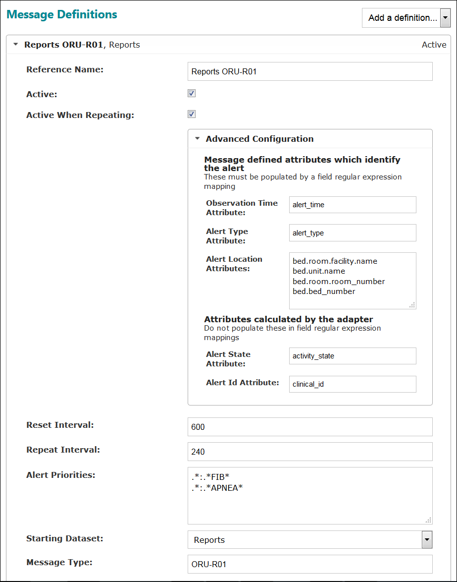
Message Definitions Configuration Fields Description Reference Name Enter a descriptive name for this message definition. This field is required.
Active Select this Active checkbox if the message type is to be used to match messages and make the message definition active in the system. Active message types are matched in the order specified in the configuration.
Discard Select this Discard checkbox to discard matching messages, instead of storing them in the dataset. This option is hidden when Active When Repeating is checked. Selecting Discard removes two configuration options: Active When Repeating, and Starting Dataset.
Active When Repeating Select the Active When Repeating checkbox if the message represents an alert that will be received repeatedly and repetitions should be ignored. This option is hidden when Discard is checked above. Complete the additional information as described in Advanced Configuration.
Advanced Configuration Click Advanced Configuration to display the alert mapping configuration fields.
The Advanced Configuration settings are displayed when the Active When Repeating box is checked, presenting a set of conditions that may be considered active as long as they keep repeating. Not every received message is saved.
Observation Time Attribute Enter the attribute that stores the time the alert was received.
Alert Type Attribute Enter the attribute that stores the type of the alert.
Alert Location Attributes Enter the attributes that store the alert's unique location.
Alert State Attribute Enter the attribute that stores the calculated current alert state.
Alert ID Attribute Enter the attribute that stores the calculated ID for the alert record.
Reset Interval Enter the time in seconds that may elapse after the last instance of a repeated alert is received before the alert should be set to inactive. The value must be between 1 and 3600 seconds.
Repeat Interval Enter the time in seconds that may elapse between repeating events, after which period a repeated alert of this message type should be recognized as a new event and a new record created in the database. The value must be between 1 and 3600 seconds.
Alert Priorities Enter an ordered list of regular expressions to be matched against the alert type value; listed in highest to lowest priority. If multiple alerts are received in the same message, the highest priority alert will be recorded as active and all other alerts will be recorded as suppressed. For example, an APNEA alert will be suppressed when a higher priority FIB alert is active.
See Understading Regular Expressions for an overview explanation and examples of Regex code and mappings.
Starting Dataset Select the starting dataset for the relative data mappings for the message definition where data for the received message should be stored. This option is hidden when Discard is checked. This field is required.
Message Type Enter the HL7 message type for this message definition in the format MessageType-Event Type, such as ORU-R01. This field is required. Enter multiple message types as a comma separated list of values. This field allows special characters -, _, or ^ to be used as separators, such as ADT-A01 or ADT^A01.
-
Complete the Message Type Segment Definitions
configuration settings.
At least one segment definition must be provided for a message definition. A segment definition will match a received segment when:
- The name of the received segment matches the name of the segment definition.
- The received segment has each field matching the regex if it is required to match.
- A repeated segment matches if any of the repeated segments match.
Note: All HL7 messages build their MSH segments with an internal segment definition. All existing MSH segment definitions are ignored.Click Add Segment Definition to create additional segments. A New Segment Definition expansion box will appear at the bottom of the segment list. Drag and drop segment definitions to re-order the list; for example, you might select the New Segment Definition and drag it to the top of the list for configuration.
Expand an existing segment definition to edit the configuration. Links at the bottom of this field are provided to clone or remove a segment definition, remove the last field definition, and add a field definition.
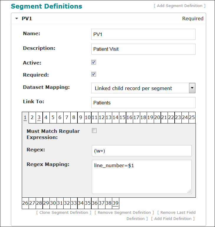
Message Type Segment Definitions Configuration Fields Description Name Enter the HL7 name for this segment definition. This field is required.
Description Enter a description of the new segment created for this message definition. This field is optional.
Active Select this checkbox if the segment definition is active for this adapter.
Required Select this checkbox if the segment definition must be matched for its message definition to be matched.
Dataset Mapping Select an option from the dropdown menu that will determine how to map the field data from segments matching this definition. Select to add the data to the parent record (taking into account segment groups), to create separate parent records for each matching segment, or to create separate linked child records for each matching segment.
The dropdown menu options display as follows:
- Add to parent record
- Parent record per segment
- Linked child record per segment
Link To The Link To field is displayed when the "Linked child record per segment" option is selected in the Dataset Mapping dropdown menu.
Enter the name of a link to a dataset, relative to the message definition's starting dataset, in which to store attribute mappings.
Field Definitions At least one field definition must be configured for a segment definition. A field definition will match a received field if the received field content matches the regular expression of the field definition. A repeated field matches if any of the repeated fields match the regular expression specified.
Links at the bottom of this field are provided to clone or remove a segment definition, remove the last field definition, and add a field definition.
Expand an existing field definition (click the tab number; e.g., 1, 2, or 3 below) to edit the configuration.
Must Match Regular Expression Check the Must Match Regular Expression checkbox to require that the field definition must be matched for its segment definition to be matched. The field definition need not be matched for the segment definition to be matched.
See Understading Regular Expressions for an overview explanation and examples of Regex code and mappings.
Regex Enter a regular expression to capture values from received field content. This field is required if the Must Match Regular Expression box is checked, and must be a valid regular expression.
See Understading Regular Expressions for an overview explanation and examples of Regex code and mappings.
Special characters determine the number of expected components and sub-components in a field. The special character '^' is used to separate components in a field, and '&' is used to separate sub-components in a component. These characters should not be used for another purpose in the regular expression.
- The HL7 component separator '^' and the sub-component separator '&' do not need to be escaped.
- The regular expression will only be matched against the number of components and sub-components specified. Extra (unspecified) components and sub-components will be discarded.
- Components and sub-components can be ignored without specifying a regular expression. As an example, the regular expression "^^(.*)" would ignore the first two components and capture the third.
-
No special consideration is needed for optional components and sub-components. If an optional component or sub-component is not in a received field, its capture group will be mapped to an empty string.
Regex Mapping Enter one or more attributes or attribute paths, one per line, to be filled with data from the above regular expression. This field is required.
See Understading Regular Expressions for an overview explanation and examples of Regex code and mappings.
Specify the regex mapping from the capture groups of the Regex above to attribute paths starting from the Clinicals dataset. Two attribute mapping patterns are supported; plain attribute list, and statement of equality.
Plain attribute list: Each item in the mapping is a simple attribute path. The first capture group of the matched regular expression is used as the value of the first attribute path in the list, and so on. The number of capture groups in the regex must match the number of attribute paths in the list. The syntax is dataset_link_attribute_name.attribute_name, or dataset_attribute_name. If this segment links to another dataset, all attribute paths used in the regex mappings implicitly start with the link used in Link To.
Statement of equality: The left-hand side of the statement is the attribute path, while the right-hand side is the value that the attribute path should be set to. On the right side, use numbered captured groups (such as $1) to reference elements matched, or literal strings. The syntax is dataset_link_attribute_name.attribute_name=LITERAL, or dataset_attribute_name=$1, or example_with_two_capture_groups=$2:$1
To build a single attribute path value from multiple fields, add a subscript to the path. The final value will be built from the various values in subscript order. For example, dataset_attr_name[0]=XXX and dataset_attr_name[1]=YYY will result in dataset_attr_name=XXXYYY.