All nodes in the cluster are all located within the same IP subnet. The active and all standby servers are Ethernet layer 2 adjacent to each other.
The layer 2 adjacent deployment provides the most direct and simplest method for the cluster to manage the VIP.
The active server on the cluster responds to connections addressed to the VIP. All external connection requests are directed and serviced by the active server. In this configuration, there is no need for a third-party server (i.e., load balancers, application delivery controllers, etc.) to manage the VIP; the cluster itself manages the VIP.
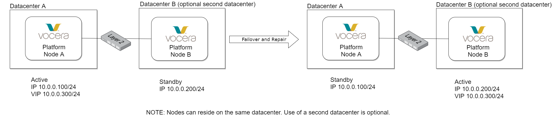
In this diagram, all nodes in the cluster are all located within the same IP subnet and may be split across datacenters depending on the customer network design. The active and all standby servers are Ethernet layer 2 adjacent to each other. Should the active node in this cluster fail, the Vocera system will automatically transfer the VIP to the standby node and continue processing data without interruption. The nodes in the cluster in this example share a VIP as they change standby and active roles.