The Vocera Outgoing WCTP Adapter rules can trigger the adapter to send messages to a WCTP Carrier Gateway.
A Vocera Outgoing WCTP Adapter rule for triggering a message to be sent may be defined against a dataset view. The rule defines the parameters used in formulating the message, to whom it should be sent, and what to do with the response.
See the Vocera Platform Administration Guide for information about working with rules. See Configuring a Vocera Outgoing WCTP Adapter for information about adapter settings.
In the Adapter Settings, configure the Rule Settings fields on a Vocera dataset to manage message delivery.
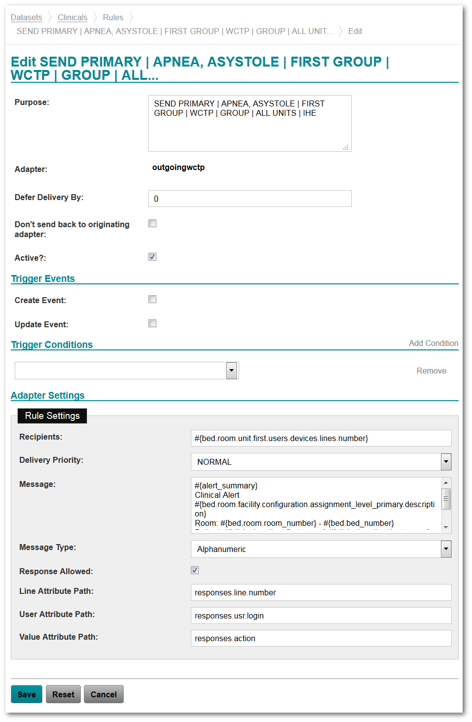
The Message Type selection controls which fields display for configuration. In the image above, the Message Type field selection is Alphanumeric, which displays the Response Allowed checkbox.
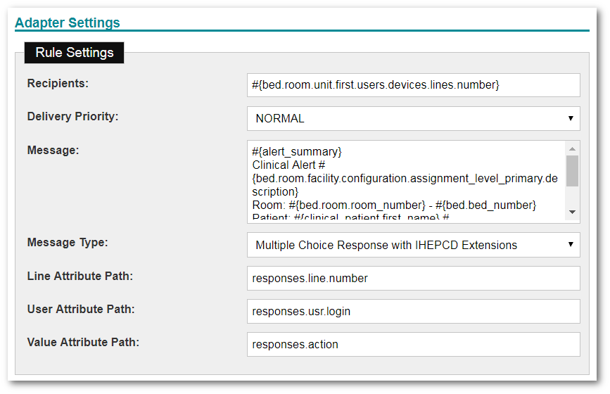
In the image below, one of the two Multiple Choice Response options is selected, which display the attribute path configuration fields for line, user, and value. See the tables below to understand all of the configuration field descriptions.
| Rule Settings | Description |
|---|---|
| Recipients |
Enter the lines to which the message should be delivered. This field is required. |
| Delivery Priority |
Select the delivery priority value to assign to the message; options in the dropdown are:
|
| Message |
Enter the message that should be delivered. This field is required. |
| Message Type |
Select the Message Type for the rule; dropdown options are:
|
| Response Allowed |
Select this checkbox to indicate whether or not responses to a message are allowed. This checkbox only displays when the Alphanumeric option is selected in the Message Type dropdown shown above. If the Response Allowed box is not checked, the Line, User, and Value Attribute Path fields described next are not available. |
| Line Attribute Path |
Enter an attribute path relative to the triggering dataset in which to store a responding line. Required if Alphanumeric and Response Allowed are selected, or if either Multiple Choice Response or Multiple Choice Response with IHEPCD Extensions is selected. |
| User Attribute Path |
Enter an attribute path relative to the triggering dataset in which to store a responding user. Required if Alphanumeric and Response Allowed are selected, or if either Multiple Choice Response or Multiple Choice Response with IHEPCD Extensions is selected. |
| Value Attribute Path |
Enter an attribute path relative to the triggering dataset in which to store a responding value. Required if Alphanumeric and Response Allowed are selected, or if either Multiple Choice Response or Multiple Choice Response with IHEPCD Extensions is selected. |
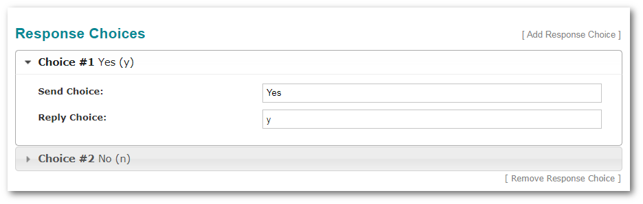
The Response Choices configuration fields display when the Message Type field is set to either Multiple Choice Response, or Multiple Choice Response with IHEPCD Extensions.
| Response Choices Configuration Field | Description |
|---|---|
| Send Choice |
Enter the string to display to a user for this choice. Send Choice is the prompt component of an MCR request. This is the value used by the ACM Alert Communicator to populate buttons, softkeys, or menu choices on the endpoint communication device for selection by the device operator. There can be multiple. |
| Reply Choice |
Enter the string to return to the enterprise host for this choice. Reply Choice is the response value component of an MCR request. This value is correlated with its same ordinal occurrence Send Choice value. |
| Add Response Choice | Click to add a response choice to the configuration. |
| Remove Response Choice | Click to remove the selected response choice from the configuration. |
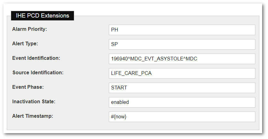
The optional IHE PCD Extensions configuration fields display when the Message Type field is set to Multiple Choice Response with IHEPCD Extensions.
| IHE PCD Extensions Configuration Field | Description |
|---|---|
| Alarm Priority |
Enter the IHE value to be sent for the alarm priority. For example:
HL7 values to automatically populate the alarm priority:
This corresponds to an observation in a PCD-04 Report Alert transaction. For more information, see Table B.8.5-1 in the IHE PCD TF Volume 2. |
| Alert Type |
Enter the IHE value to be sent for the alert type. For example:
HL7 values to automatically populate the alert type:
This corresponds to an observation in a PCD-04 Report Alert transaction. For more information, see Table B.8.5-1 in the IHE PCD TF Volume 2. |
| Event Identification |
Enter the IHE value to be sent for the MDC formatted event identification. The MDC event code should be taken from the IEEE 11073-10101 nomenclature for event codes. The event code is the specific identification of the alert. HL7 values to automatically populate the event identification:
The event identification is the MDC event code for the alert. This corresponds to an observation in a PCD-04 Report Alert transaction. For more information, see Table B.8.5-1 in the IHE PCD 4670 TF Volume 2. |
| Source Identification |
Enter the IHE value to be sent for the source system identification. In the case of physiologic alarm type of alerts, this is the associated MDC value for the alert. In the case of technical alarm type alerts and advisory type alerts, this is 196616^MDC_EVT_ALARM^MDC and OBX-5 contains the specific identification of the alert. The source identification is the physiological measurement or technical source responsible for the alert. This corresponds to an observation in a PCD-04 Report Alert transaction. For more information, see Table B.8.5-1 in the IHE PCD TF Volume 2. |
| Event Phase |
Enter the IHE value to be sent for the event phase. The event phase describes the stimulus for the message which can be the beginning, end, or some other state, or state transition of the alert. For example:
HL7 value to automatically populate the event phase:
The event phase corresponds to an observation in a PCD-04 Report Alert transaction. An Alert Manager can use this field to inform an Alert Communicator that a PCD-06 message was sent as a result of an escalation or deescalation. For more information, see Table B.8.5-1 in the IHE PCD TF Volume 2. |
| Inactivation State |
Enter the IHE value to be sent for the inactivation state. The inactivation state reflects the current state of the visual and aural alert indications at the alert source. HL7 value to automatically populate the inactivation state:
This corresponds to an observation in a PCD-04 Report Alert transaction. For more information, see Table B.8.5-1 in the IHE PCD TF Volume 2. |
| Alert Timestamp |
Enter the IHE value to be sent for the alert timestamp. This can be any value stored in the system as Date Time. HL7 values to automatically populate the alert timestamp:
The alert timestamp is the timestamp for an alert indication according to the Alert Manager. This corresponds to a value in a PCD-04 Report Alert transaction, but it is in the format of a WCTP conformant timestamp (yyyy-mm-ddThh:mm:ss.tt). For more information, see Section B.8.7 in the IHE PCD TF Volume 2. |
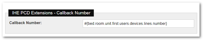
| Callback Number Configuration Field | Description |
|---|---|
| Callback Number | Enter the value to be sent for the IHE Callback Phone Number. This field is the telephone number for reporting a status or a result using the standard format with extension and/or beeper number when applicable. This can be used to pass the nurse call system patient station telephony call back information to the caregiver. If the structure of the telephony dial string is not known, then the call back number should be in the Unformatted Telephone number (ST) component of the field. |
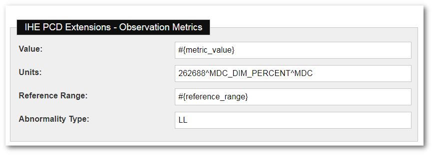
| Observation Metrics Configuration Field | Description |
|---|---|
| Value |
Enter the IHE value (as an attribute) to be sent for the value of a report alert transaction. HL7 value to automatically populate the value:
This corresponds to an observation in a PCD-04 Report Alert transaction. For more information, see Section B.8.5 in the IHE PCD TF Volume 2 |
| Units |
Enter the IHE value to be sent for the measurement type of the value of an alert. If a value is specified, the units should also be specified. IHE requires units to be specified as MDC encoded values. If different units are expected for the same alert, the MDC value can be provided via an attribute transformation on the attribute that the unit is captured on. HL7 value to automatically populate the units:
This corresponds to an observation in a PCD-04 Report Alert transaction. For more information, see Section B.8.5 in the IHE PCD TF Volume 2. |
| Reference Range |
Enter the IHE value (as an attribute) to be sent for the alert range set in the alarming device. HL7 value to automatically populate the reference range:
This corresponds to a value in a PCD-04 Report Alert transaction. For more information, see Section B.8.5 in the IHE PCD TF Volume 2. |
| Abnormality Type |
Enter the IHE value to be sent for the abnormality type which indicates the type of abnormality described by this alert. For example:
HL7 value to automatically populate the abnormality type:
This corresponds to an observation in a PCD-04 Report Alert transaction. For more information, see Section B.8.5 in the IHE PCD TF Volume 2. |
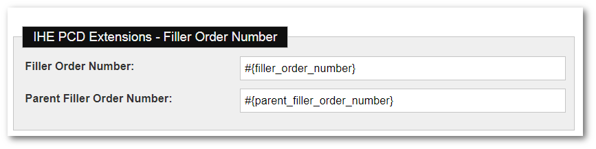
| Filler Order Number Configuration Field | Description |
|---|---|
| Filler Order Number |
Enter the IHE value (as an attribute) to be sent for the filler order number, which is the unique identifier for status updates to an alert indication. HL7 values to automatically populate the filler order number:
The filler order number is the unique identifier for status updates to an alert indication. This corresponds to a value in a PCD-04 Report Alert transaction. For more information, see Section B.7.1 in the IHE PCD TF Volume 2. |
| Parent Filler Order Number |
Enter the IHE value (as an attribute) to be sent for the filler order number, which is the unique identifier for the original alert indication. HL7 values to automatically populate the parent filler order
number:
The parent filler order number is the unique identifier for the original alert indication. This corresponds to a value in a PCD-04 Report Alert transaction. For more information, see Section B.7.1 in the IHE PCD TF Volume 2. |
The location of an alert is defined by one or more location elements. These location elements are modeled from the FHIR 8 Location resource. There are attributes for the identifier, description, type, and physical type. Refer to the FHIR (Health Level Seven International) standard for descriptions and available values of these attributes.
For Bed Location, PV1-3.2 maps to a wctp-IHEPCDACMLocation element with a physical type attribute of “bd” as defined in the FHIR Location Physical Type value set.
For Room Location, PV1-3.2 maps to a wctp-IHEPCDACMLocation element with a physical type attribute of “ro” as defined in the FHIR Location Physical Type value set.
For Unit Location, PV1-3.3 maps to a wctp-IHEPCDACMLocation element with a physical type attribute of “hu” as defined in the FHIR Location Physical Type value set.
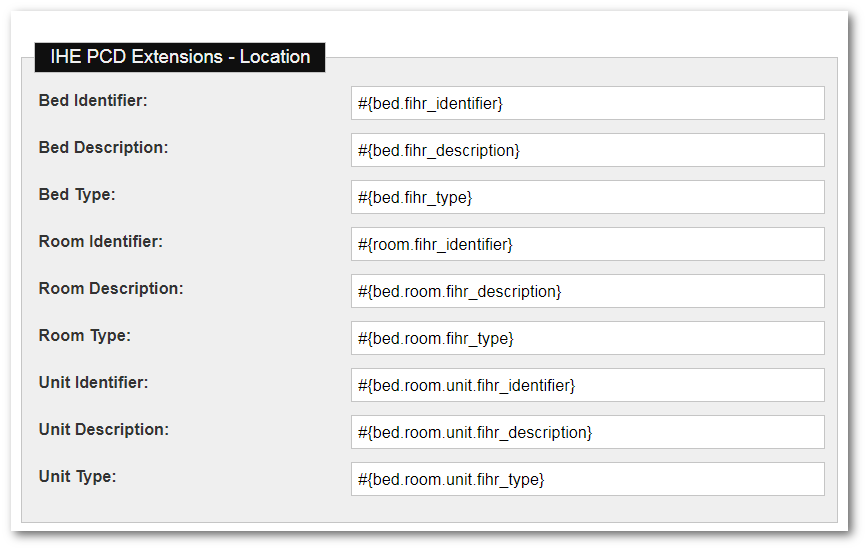
| Location Configuration Field | Description |
|---|---|
| Bed Identifier | Enter the unique code or number identifying the bed as defined by FIHR. |
| Bed Description | Enter the description of the bed, which helps in finding or referencing the place. |
| Bed Type | Enter the type of function performed at the bed as defined by FIHR. |
| Room Identifier | Enter the unique code or number identifying the room as defined by FIHR. |
| Room Description | Enter the description of the room, which helps in finding or referencing the place. |
| Room Type | Enter the type of function performed at the room as defined by FIHR. |
| Unit Identifier | Enter the unique code or number identifying the unit as defined by FIHR. |
| Unit Description | Enter the description of the unit, which helps in finding or referencing the place. |
| Unit Type | Enter the type of function performed at the unit as defined by FIHR. |
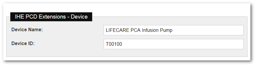
| Device Configuration Field | Description |
|---|---|
| Device Name | Enter the IHE value to be sent for the name of the participating device. |
| Device ID | Enter the IHE value to be sent for the ID of the participating device, which is the Equipment Instance Identifier. |
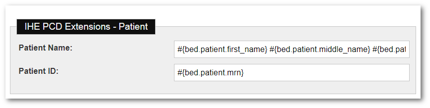
| Patient Configuration Field | Description |
|---|---|
| Patient Name | Enter the IHE value to be sent for the name of the participating patient. |
| Patient ID | Enter the IHE value to be sent for the ID of the participating patient. |