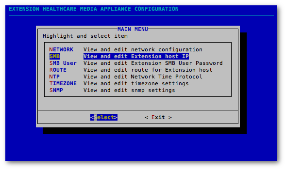
The Media appliance is configured by navigating a simple text-based menu, Vocera Media Appliance Main Menu, accessed via a terminal window.
Network
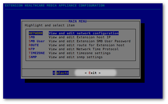
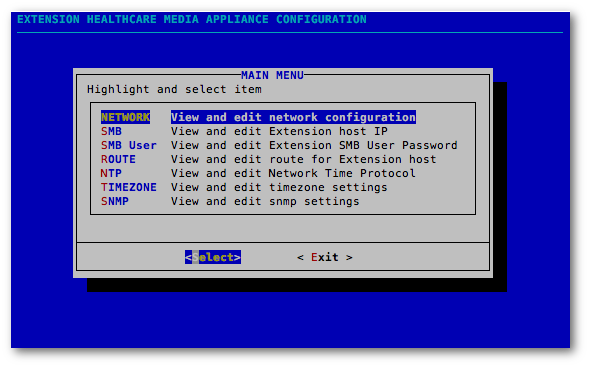
In the Main Menu, use the keyboard up/down arrows to navigate the options list; select Network as shown below. Then use the keyboard left/right arrows to toggle between Select and Exit; highlight the Select option and press Return on the keyboard.
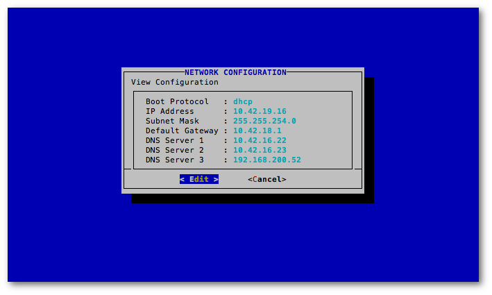
The system is set up with DHCP configuration by default to provide access to the server. Now the IP address must be set to the customer's static address.
Use the keyboard left/right arrows to toggle between Edit and Cancel; highlight the Edit option and press Return on the keyboard.
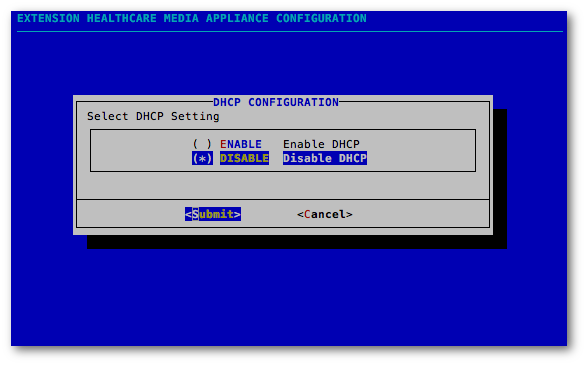
In the DHCP Configuration window, highlight Disable and press the Space key to select this option. Then press Tab to highlight Submit and press the Return key to actually disable DHCP.
The highlighted selection must display the asterisk in the parentheses in order to choose the option. In the image below, although Disable is highlighted, the Enable option is active.

You must press the Space key to ensure the asterisk displays in the highlighted Disable option as shown here, before selecting Submit.
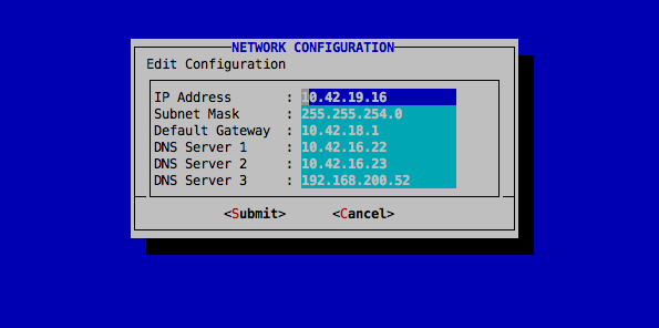
In the Network Configuration window, enter the permanent address for the Media appliance. Obtain the IP address or the subnet from the hospital administrator to enter the correct information.
Press the keyboard Tab key to access the Submit and Cancel options, and then use the keyboard up/down arrows to toggle to select Submit. Press Return to submit the configuration settings.
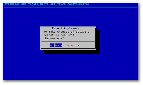
Highlight Yes and press the Return key to reboot the appliance. Reboot is required after changing the IP address. If needed, select No to make additional configuration changes and reboot the appliance later.
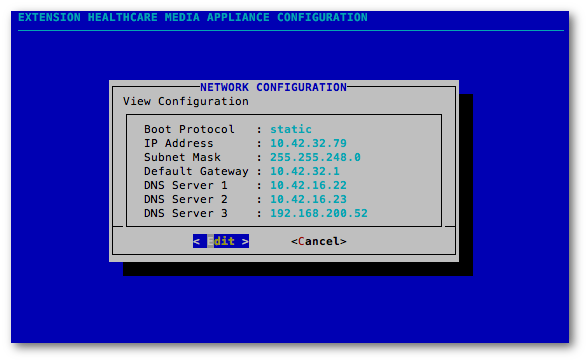
The final configuration will use a static Boot protocol as shown below.
SMB
In the Main Menu, highlight SMB and then click Select.
The Engage Host IP Configuration is optional. If no IP address, or range of IP addresses, is entered in this field, then any computer will be able to connect to the Media appliance. If the client chooses to limit the IP addresses that can connect to the Media appliance, then these IP addresses are identified here. To input these IP addresses, select Edit in the View Engage Host IP Configuration window.
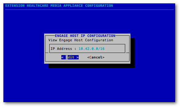
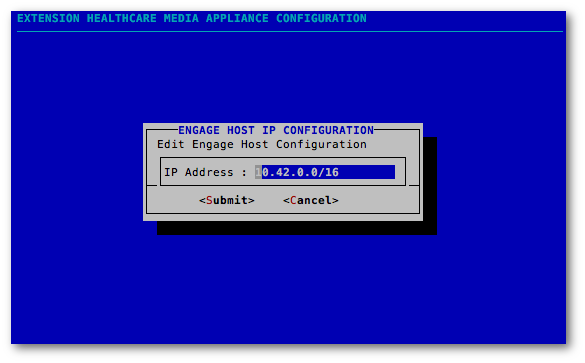
In the Edit Engage Host IP Configuration window, enter the exact IP address for the Engage appliance (or the subnet) and then select Submit. If a range of IP addresses are identified, they are stated as four octets followed by the CIDR; e.g., 10.42.22.0/24. A single IP address can be specified with a CIDR value of 32; e.g., 10.42.22.123/32.
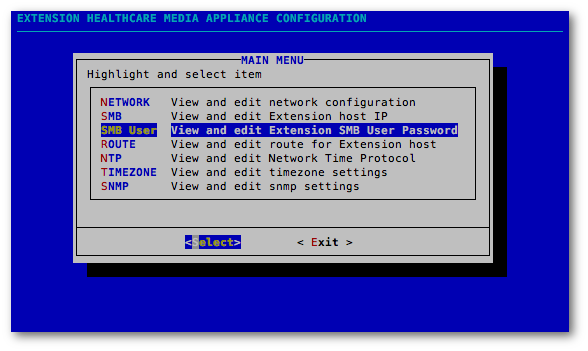
SMB User
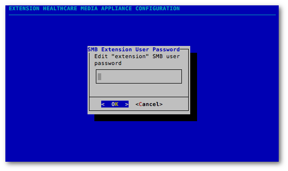
In the Main Menu, highlight the SMB User option and then click Select.
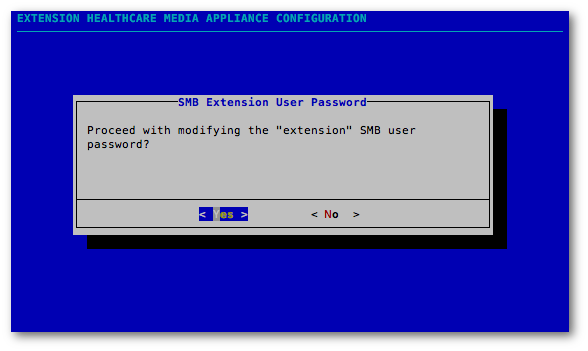
Select Yes to set the user password required by the Media adapter on the Engage appliance.
In the SMB Extension User Password window, type the desired password for the SMB User and then click OK. Any password requirements are fulfilled in this SMB User password configuration, and will be matched in the Storage Password field in the Media adapter.
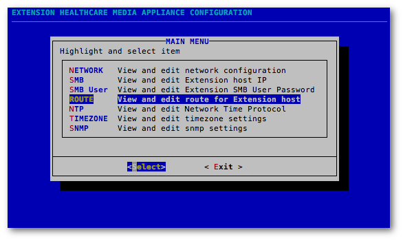
Route
In the Main Menu, select Route if a gateway is required to communicate with the Engage appliance. This configuration option is generally not needed, because the Media appliance and the Engage appliance should both be located on the same broadcast domain / Layer 2 adjacency.
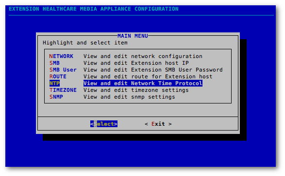
NTP
In the Main Menu, highlight NTP and then click Select.
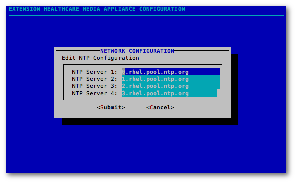
In the View NTP Server Configuration window, select Edit.
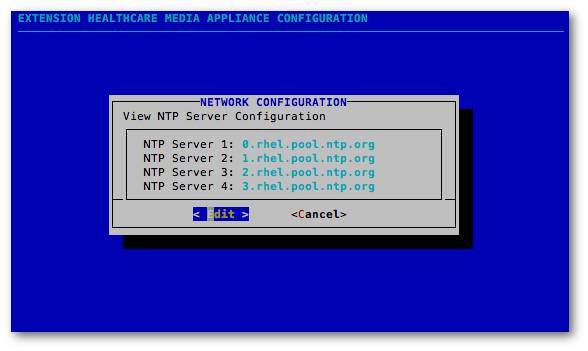
In the Edit NTP Server Configuration window, configure the IP address of the Network Time Protocol sources and then select Submit. Ensure that the values entered here match those on the Engage appliance to synchronize time across the two appliances.
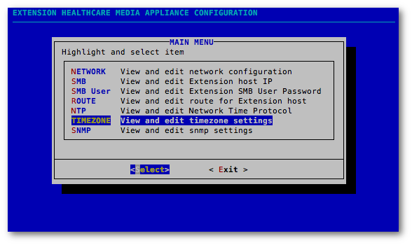
Timezone
In the Main Menu, highlight Timezone and then click Select.
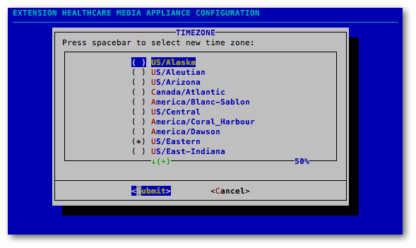
In the Timezone window, select the timezone used by the Engage appliance and then click Submit. If the timezone needs to be changed, highlight the correct zone using the arrow keys, and then hit the Space bar to select that zone. In the example below, US/Eastern is the configured Media timezone.
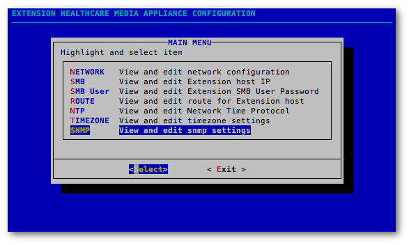
SNMP
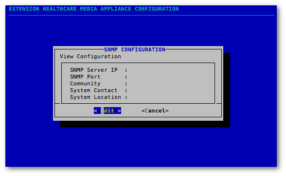
In the Main Menu, highlight SNMP and click Select.
In the View SNMP Configuration window, select Edit.
In the Edit SNMP Configuration window, configure SNMP to match the Engage appliance settings. This enables Engage to access error notifications from the Media appliance. The SNMP Server, SNMP Port, and Community fields must be completed.
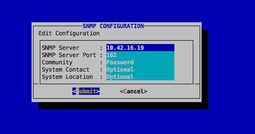
| SNMP Configuration Field | Description |
|---|---|
| SNMP Server | This field contains the IP Address or the FQDN within the DNS of the facility's Monitoring Tool. |
| SNMP Port | This field contains the Port number where the Monitoring Tool is located, usually 162. |
| Community | This field contains the password that is utilized by the SNMP Monitoring Tool. |
| System Contact | This field is optional. |
| System Location | This field is optional. |
When SNMP is configured, select Tab, then press the left/right arrows on the keyboard to toggle between Submit and Cancel, and finally press the Return key to select Submit.

In the Main Menu, select Exit to immediately close the Extension Healthcare Media Appliance Configuration menu. This action returns you to the terminal window.